")

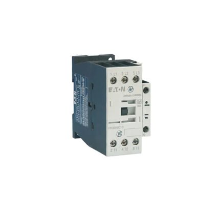
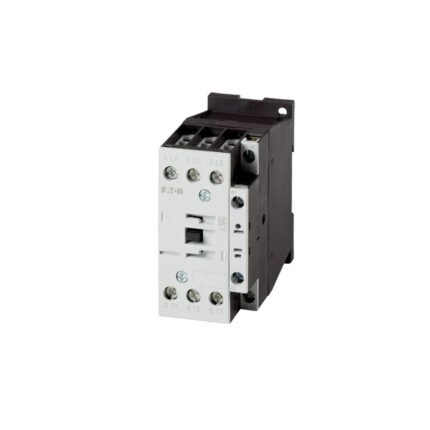
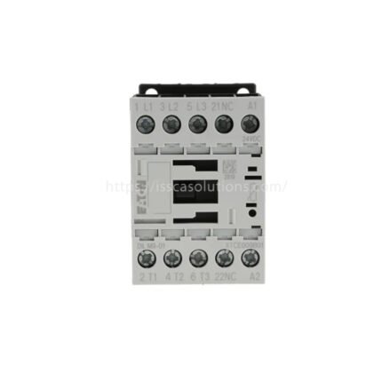
276697 Código de modelo: DILM9-10(220V50/60HZ) Contactor Eaton DILM
$48.00
- Número de pieza: 276697 DILM9-10(220V50/60HZ)
- Fabricante:Eaton
- Disponibilidad: en stock
- Tiempo estimado de entrega: Normalmente se envía en 1-5 días laborables
- Estado: Nuevo
- Garantía :12 meses
Descripción
Especificaciones generales
| Nombre del producto | Eaton Moeller® series DILM contactor |
| Número de catálogo | 276697 |
| Código de modelo | DILM9-10(220V50/60HZ) |
| EAN | 4015082766979 |
| Longitud/profundidad del producto | 75 mm |
| Altura del producto | 68 mm |
| Anchura del producto | 45 mm |
| Peso del producto | 0.24 kg |
| Certificaciones | IEC/EN 60947 IEC/EN 60947-4-1 UL File No.: E29096 UL Category Control No.: NLDX UL CSA CSA File No.: 012528 VDE 0660 CSA-C22.2 No. 60947-4-1-14 CSA Class No.: 2411-03, 3211-04 CE UL 60947-4-1 |
| Catalog Notes | Contacts according to EN 50012 |
Features & Functions
| Number of poles | Three-pole |
General
| Aplicación | Contactors for Motors |
| Frame size | FS1 |
| Lifespan, mechanical | 7,000,000 Operations (Coil 50/60 Hz) 10,000,000 Operations (AC operated) |
| Operating frequency | 9000 mechanical Operations/h (AC operated) |
| Overvoltage category | III |
| Pollution degree | 3 |
| Product category | Contactors |
| Protection | Finger and back-of-hand proof, Protection against direct contact when actuated from front (EN 50274) |
| Rated impulse withstand voltage (Uimp) | 8000 V AC |
| Resistance per pole | 2.5 mΩ |
| Suitable for | Also motors with efficiency class IE3 |
| Utilization category | AC-1: Non-inductive or slightly inductive loads, resistance furnaces AC-3: Normal AC induction motors: starting, switch off during running AC-4: Normal AC induction motors: starting, plugging, reversing, inching |
| Tipo de tensión | CA |
Ambient conditions, mechanical
| Shock resistance | 3.4 g, N/O auxiliary contact, Mechanical, according to IEC/EN 60068-2-27 when tabletop-mounted, Half-sinusoidal shock 10 ms 3.4 g, N/C auxiliary contact, Mechanical, according to IEC/EN 60068-2-27 when tabletop-mounted, Half-sinusoidal shock 10 ms 10 g, N/O main contact, Mechanical, according to IEC/EN 60068-2-27, Half-sinusoidal shock 10 ms 7 g, N/O auxiliary contact, Mechanical, according to IEC/EN 60068-2-27, Half-sinusoidal shock 10 ms 5 g, N/C auxiliary contact, Mechanical, according to IEC/EN 60068-2-27, Half-sinusoidal shock 10 ms 5.7 g, N/O main contact, Mechanical, according to IEC/EN 60068-2-27 when tabletop-mounted, Half-sinusoidal shock 10 ms |
Climatic environmental conditions
| Ambient operating temperature – min | -25 °C |
| Ambient operating temperature – max | 60 °C |
| Ambient operating temperature (enclosed) – min | 25 °C |
| Ambient operating temperature (enclosed) – max | 40 °C |
| Ambient storage temperature – min | 40 °C |
| Ambient storage temperature – max | 80 °C |
| Climatic proofing | Damp heat, cyclic, to IEC 60068-2-30 Damp heat, constant, to IEC 60068-2-78 |
Electro Magnetic Compatibility
| Emitted interference | According to EN 60947-1 |
| Interference immunity | According to EN 60947-1 |
Terminal capacities
| Terminal capacity (flexible with ferrule) | 2 x (0.75 – 2,5) mm² 1 x (0.75 – 2.5) mm² 2 x (0.75 – 2.5) mm² |
| Terminal capacity (solid) | 2 x (0.75 – 2.5) mm² 1 x (0.75 – 4) mm² |
| Terminal capacity (solid/stranded AWG) | Single 18 – 10, double 18 – 14 |
| Stripping length (main cable) | 10 mm |
| Stripping length (control circuit cable) | 10 mm |
| Screw size | M3.5, Terminal screw |
| Screwdriver size | 2, Terminal screw, Pozidriv screwdriver 0.8 x 5.5/1 x 6 mm, Terminal screw, Standard screwdriver |
| Tightening torque | 1.2 Nm, Screw terminals |
Electrical Rating
| Rated breaking capacity at 220/230 V | 90 A |
| Rated breaking capacity at 380/400 V | 90 A |
| Rated breaking capacity at 500 V | 70 A |
| Rated breaking capacity at 660/690 V | 50 A |
| Rated operational current (Ie) at AC-1, 380 V, 400 V, 415 V | 22 A |
| Rated operational current (Ie) at AC-3, 220 V, 230 V, 240 V | 9 A |
| Rated operational current (Ie) at AC-3, 380 V, 400 V, 415 V | 9 A |
| Rated operational current (Ie) at AC-3, 440 V | 9 A |
| Rated operational current (Ie) at AC-3, 500 V | 7 A |
| Rated operational current (Ie) at AC-3, 660 V, 690 V | 5 A |
| Rated operational current (Ie) at AC-4, 220 V, 230 V, 240 V | 6 A |
| Rated operational current (Ie) at AC-4, 400 V | 6 A |
| Rated operational current (Ie) at AC-4, 500 V | 5 A |
| Rated operational current (Ie) at AC-4, 660 V, 690 V | 4.5 A |
| Rated operational current (Ie) at DC-1, 60 V | 20 A |
| Rated operational current (Ie) at DC-1, 110 V | 20 A |
| Rated operational current (Ie) at DC-1, 220 V | 15 A |
| Rated insulation voltage (Ui) | 690 V |
| Rated operational current (Ie) at AC-1, 380 V, 400 V, 415 V | 22 A |
| Rated operational power at AC-3, 240 V, 50 Hz | 3 kW |
| Rated operational power at AC-3, 380/400 V, 50 Hz | 4 kW |
| Rated operational power at AC-3, 415 V, 50 Hz | 5.5 kW |
| Rated operational power at AC-4, 220/230 V, 50 Hz | 1.5 kW |
| Rated operational power at AC-4, 240 V, 50 Hz | 1.6 kW |
| Rated operational power at AC-4, 415 V, 50 Hz | 2.8 kW |
| Rated operational power at AC-4, 440 V, 50 Hz | 3 kW |
| Rated operational power at AC-4, 500 V, 50 Hz | 2.8 kW |
| Rated operational power at AC-4, 660/690 V, 50 Hz | 3.6 kW |
| Rated operational voltage (Ue) at AC – max | 690 V |
Short-circuit rating
| Short-circuit current rating (basic rating) | 5 kA, SCCR (UL/CSA) 45 A, max. Fuse, SCCR (UL/CSA) 60 A, max. CB, SCCR (UL/CSA) |
| Short-circuit current rating (high fault at 480 V) | 16 A, max. CB, SCCR (UL/CSA) 30/100 kA, Fuse, SCCR (UL/CSA) 65 kA, CB, SCCR (UL/CSA) 25 A, Class RK5/ 20 A Class J, max. Fuse, SCCR (UL/CSA) |
| Short-circuit current rating (high fault at 600 V) | 25 A, Class RK5/20 A, Class J, max. Fuse, SCCR (UL/CSA) 30/100 kA, Fuse, SCCR (UL/CSA) |
| Short-circuit protection rating (type 1 coordination) at 400 V | 35 A gG/gL |
| Short-circuit protection rating (type 1 coordination) at 690 V | 20 A gG/gL |
| Short-circuit protection rating (type 2 coordination) at 400 V | 20 A gG/gL |
| Short-circuit protection rating (type 2 coordination) at 690 V | 16 A gG/gL |
Conventional thermal current
| Conventional thermal current Ith (1-pole, enclosed) | 45 A |
| Conventional thermal current Ith (3-pole, enclosed) | 18 A |
| Conventional thermal current Ith at 55°C (3-pole, open) | 21 A |
| Conventional thermal current Ith of main contacts (1-pole, open) | 50 A |
Switching capacity
| Switching capacity (main contacts, general use) | 20 A, Maximum motor rating (UL/CSA) |
| Switching capacity (auxiliary contacts, general use) | 1 A, 250 V DC, (UL/CSA) 10 A, 600 V AC, (UL/CSA) |
| Switching capacity (auxiliary contacts, pilot duty) | A600, AC operated (UL/CSA) P300, DC operated (UL/CSA) |
Switching time
| Arcing time | 10 ms |
| Switching time (AC operated, make contacts, closing delay) – min | 15 ms |
| Switching time (AC operated, make contacts, closing delay) – max | 21 ms |
| Switching time (AC operated, make contacts, opening delay) – min | 9 ms |
| Switching time (AC operated, make contacts, opening delay) – max | 18 ms |
Magnet system
| Drop-out voltage | AC operated: 0.6 – 0.3 x UC, AC operated |
| Duty factor | 100 % |
| Pick-up voltage | 0.8 – 1.1 V AC x Uc |
| Power consumption, pick-up, 50 Hz | 25 VA, Dual-frequency coil in a cold state and 1.0 x Us 27 VA, Dual-frequency coil in a cold state and 1.0 x Us |
| Power consumption, pick-up, 60 Hz | 25 VA, Dual-frequency coil in a cold state and 1.0 x Us 27 VA, Dual-frequency coil in a cold state and 1.0 x Us |
| Power consumption, sealing, 50 Hz | 1.2 W, Dual-frequency coil in a cold state and 1.0 x Us 1.4 W, Dual-frequency coil in a cold state and 1.0 x Us |
| Power consumption, sealing, 60 Hz | 1.4 W, Dual-frequency coil in a cold state and 1.0 x Us 1.2 W, Dual-frequency coil in a cold state and 1.0 x Us 4.2 VA, Dual-frequency coil in a cold state and 1.0 x Us, at 60 Hz 3.3 VA, Dual-frequency coil in a cold state and 1.0 x Us, at 60 Hz |
| Rated control supply voltage (Us) at AC, 50 Hz – min | 220 V |
| Rated control supply voltage (Us) at AC, 50 Hz – max | 220 V |
| Rated control supply voltage (Us) at AC, 60 Hz – min | 220 V |
| Rated control supply voltage (Us) at AC, 60 Hz – max | 220 V |
| Rated control supply voltage (Us) at DC – min | 0 V |
| Rated control supply voltage (Us) at DC – max | 0 V |
Motor Rating
| Assigned motor power at 115/120 V, 60 Hz, 1-phase | 0.5 HP |
| Assigned motor power at 200/208 V, 60 Hz, 3-phase | 3 HP |
| Assigned motor power at 230/240 V, 60 Hz, 1-phase | 1.5 HP |
| Assigned motor power at 230/240 V, 60 Hz, 3-phase | 3 HP |
| Assigned motor power at 460/480 V, 60 Hz, 3-phase | 5 HP |
| Assigned motor power at 575/600 V, 60 Hz, 3-phase | 7.5 HP |
Communication
| Connection to SmartWire-DT | No |
Contacts
| Number of contacts (normally open contacts) | 1 |
| Number of auxiliary contacts (normally closed contacts) | 0 |
| Number of auxiliary contacts (normally open contacts) | 1 |
Safety
| Safe isolation | 400 V AC, Between coil and contacts, According to EN 61140 400 V AC, Between the contacts, According to EN 61140 |
Special purpose ratings
| Special purpose rating of ballast electrical discharge lamps | 18 A (480V 60Hz 3phase, 277V 60Hz 1phase) 18 A (600V 60Hz 3phase, 347V 60Hz 1phase) |
| Special purpose rating of definite purpose rating | 54 A, LRA 480 V 60 Hz 3-ph, 100,000 cycles acc. to UL 1995, (UL/CSA) 9 A, FLA 480 V 60 Hz 3-ph, 100,000 cycles acc. to UL 1995, (UL/CSA) |
| Special purpose rating of elevator control | 6.1 A, 600 V 60 Hz 3-ph, (UL/CSA) 2 HP, 200 V 60 Hz 3-ph, (UL/CSA) 4.8 A, 480 V 60 Hz 3-ph, (UL/CSA) 5 HP, 600 V 60 Hz 3-ph, (UL/CSA) 2 HP, 240 V 60 Hz 3-ph, (UL/CSA) 7.8 A, 200 V 60 Hz 3-ph, (UL/CSA) 6.8 A, 240 V 60 Hz 3-ph, (UL/CSA) 3 HP, 480 V 60 Hz 3-ph, (UL/CSA) |
| Special purpose rating of refrigeration control (CSA only) | 10 A, FLA 480 V 60 Hz 3phase; (CSA) 60 A, LRA 480 V 60 Hz 3phase; (CSA) 60 A, LRA 600 V 60 Hz 3phase; (CSA) 10 A, FLA 600 V 60 Hz 3phase; (CSA) |
| Special purpose rating of resistance air heating | 18 A, 480 V 60 Hz 3phase, 277 V 60 Hz 1phase, (UL/CSA) 18 A, 600 V 60 Hz 3phase, 347 V 60 Hz 1phase, (UL/CSA) |
| Special purpose rating of tungsten incandescent lamps | 14 A, 600 V 60 Hz 3phase, 347 V 60 Hz 1phase, (UL/CSA) 14 A, 480 V 60 Hz 3phase, 277 V 60 Hz 1phase, (UL/CSA) |
Design verification
| Equipment heat dissipation, current-dependent Pvid | 0 W |
| Heat dissipation capacity Pdiss | 0 W |
| Rated operational current for specified heat dissipation (In) | 9 A |
| 10.2.2 Corrosion resistance | Meets the product standard’s requirements. |
| 10.2.3.1 Verification of thermal stability of enclosures | Meets the product standard’s requirements. |
| 10.2.3.2 Verification of resistance of insulating materials to normal heat | Meets the product standard’s requirements. |
| 10.2.3.3 Resist. of insul. mat. to abnormal heat/fire by internal elect. effects | Meets the product standard’s requirements. |
| 10.2.4 Resistance to ultra-violet (UV) radiation | Meets the product standard’s requirements. |
| 10.2.5 Lifting | Does not apply, since the entire switchgear needs to be evaluated. |
| 10.2.6 Mechanical impact | Does not apply, since the entire switchgear needs to be evaluated. |
| 10.2.7 Inscriptions | Meets the product standard’s requirements. |
| 10.3 Degree of protection of assemblies | Does not apply, since the entire switchgear needs to be evaluated. |
| 10.4 Clearances and creepage distances | Meets the product standard’s requirements. |
| 10.5 Protection against electric shock | Does not apply, since the entire switchgear needs to be evaluated. |
| 10.6 Incorporation of switching devices and components | Does not apply, since the entire switchgear needs to be evaluated. |
| 10.7 Internal electrical circuits and connections | Is the panel builder’s responsibility. |
| 10.8 Connections for external conductors | Is the panel builder’s responsibility. |
| 10.9.2 Power-frequency electric strength | Is the panel builder’s responsibility. |
| 10.9.3 Impulse withstand voltage | Is the panel builder’s responsibility. |
| 10.9.4 Testing of enclosures made of insulating material | Is the panel builder’s responsibility. |
| 10.10 Temperature rise | The panel builder is responsible for the temperature rise calculation. Eaton will provide heat dissipation data for the devices. |
| 10.11 Short-circuit rating | Is the panel builder’s responsibility. The specifications for the switchgear must be observed. |
| 10.12 Electromagnetic compatibility | Is the panel builder’s responsibility. The specifications for the switchgear must be observed. |
| 10.13 Mechanical function | The device meets the requirements, provided the information in the instruction leaflet (IL) is observed. |
Información adicional
| Peso | 1 kg |
|---|
Valoraciones (0)
Debes acceder para publicar una valoración.
Envío y entrega


Valoraciones
No hay valoraciones aún.